(I should explain that model, but I won't be referring to it again in this entry, so I won't for now. See the link above.)
The next (and final) iteration of this example model makes use of functions, function application, and memoization, so I guess I'll work on those in order starting with function definitions and application.
Experimental plan
Wiring semantics
As usual, the visuals won't be directly executed, but rendered with enough precision to hint at a sensible semantics. Here's what I'm thinking.
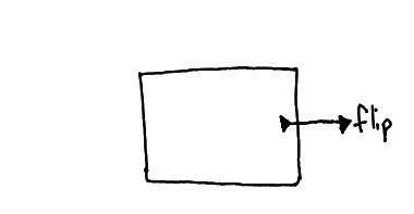
A function definition is drawn as a box. The box is analogous to function() { … } in JavaScript. Wires interact with the boundaries of the box in a few ways:
Wire direction
Connected outside?
Connected inside?
Diagram
Purpose
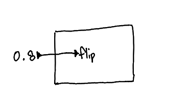
Entering
✓
✓
A captured value. These wires can come from enclosing scopes, but not disjoint ones.
This diagram is like defining a global constant 0.8 and referring to it inside the function as an argument to flip.
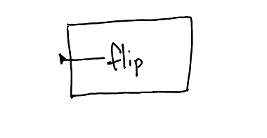
Entering
✓
A function parameter, like the x in function (x) { … }. One end of the wire is unplugged until the function is used. Makes sense.
This diagram is like calling flip(x) inside a function with an argument named "x".
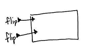
Entering
✓
A function application, like f(x), where x is the value carried by the wire. Multiple wires all take part of the same function application, like f(a, b, c).
This diagram is like calling f(flip(), flip()). See the note below about argument ordering.
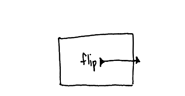
Exiting
✓
The value to return. There can be only one of these per box.
This diagram is like writing return flip().
Exiting
✓
Carries the returned value.
This diagram is like flip(f()).
When you need to refer to the function itself, like to pass it to a map(…) or whatever, you draw a wire starting at the edge of the box itself, as opposed to a wire that crosses over the edge.
I arrived at this design with two use cases in mind:
Anonymous functions used in one place. Like the one in this snippet that evaluates to an array of the results of calling flip() 10 times:
repeat(10, function() { flip() })
I wanted using functions like this to be easy: draw a box, put stuff in it, freely pull in wires with values from the surrounding context to capture them, then draw a wire connecting the function box itself to the node that needs a callback. Quick and easy?
Named functions intended for reuse. At the function definition, you don't know where wires connected to the outside go, so you drape them over the edge of the box and they'll be rendered with an end cap like “…” or something to indicate that they go… somewhere. This is consistent with the way other nodes work (like "flip") whose definitions aren't visible: you pull wires into and out of them, without really knowing what they connect to on the inside.
If a function has multiple wires going into it, how does the function decide which one to use for which purpose? In function(a, b) { … }, the arguments have names to tell them apart. We need something like that.
The direction the wire comes from seems important for some functions. For example, there's a strong directional component to the left and right sides to a “<” node.
But in repeat(count, fn)? In textual language, I forget the order of arguments of functions like that all the time. Enforcing an order makes code harder to write, but I don't know if it helps readability very much. (Would there be harm in defining both repeat(count, fn)andrepeat(fn, count)?) In the visual language I'm designing, I don't think it would be confusing to see count come from the left sometimes and right in others. You can see the numbers going in.
So there are options. In some cases, it seems reasonable for us to automatically determine which wire is which based on the values coming in ("that's a number—must be the number of times to repeat"). In other cases, maybe we use the location of the wire (“<”). In other cases, maybe we can draw on an RCA cable metaphor and use color, or a cable tag metaphor where you write down what the values on that wire are for. Something to think about later!
Which interesting new model will I implement?
I don't have a particular model in mind. I'll throw together some code that uses functions. Whatever. I just need to see functions defined and applied on the screen.
Observations and data
How I add a new language feature
I've added new language constructs for a few entries in a row, and I noticed that a pattern has emerged in how I do it:
Sketch a new model in my paper notebook, with the same nodes-and-wires representation as I want on the screen.
(Looking back, starting on paper is why nodes are currently just words floating in space. I don't draw borders or backgrounds on paper, and that translated directly to the screen representation.)
(Looking back further, I realize I'm drawing on the aesthetics of the Princeton Sound Lab software I worked on, especially sndpeek and TAPESTREA. Not really where I want to stay, but it works for now.)
Delete all remnants of the previous model from the source code, except the pieces that made it into the helper classes that I use for drawing nodes and wires and charts and whatnot. Start with a blank canvas every time.
Translate the model to the screen using Three.js graphics primitives. I even add placeholder charts of fake data everywhere that I'll want a real one later.
Write a rejection sampler for the model in TypeScript. To write a rejection sampler for a model where every setting of random variables is either valid or invalid (i.e. the only likelihoods are 0 and 1), all I have to do is write it like a normal, deterministic program and return early from any execution trace where a condition is false. So this step is easy.
Rejection sampling is more inefficient the less informative the priors are, because so few of the samples end up satisfying all the conditions. But for the models I've wanted to use so far, JavaScript has been fast enough for this not to be a problem. ¯\_(ツ)_/¯
Hook the charts up to the output of the Sampler.
So that's what I did this time, too.
I don't need to actually load and save models for what I'm trying to learn.
Stage 1: anonymous function, used in one place
I decided to implement this model first:
sum(repeat(3, function() { flip() }))
Its output is the sum of three coin flips, where heads is 1 and tails is 0.
(When I step outside my head, I can see how bizarre that statement is, and yet, I've written so many similar models that it seems like the most natural thing in the world to do. That mismatch is going to cause problems in how I talk about this language with others, and that's is why I'm trying to get as far from coin-flipping as possible as quickly as possible.)
Anyway, I translated that model like this:
Some thoughts:
It's a symptom of my coin-flipping brain rot that the arrays contain "T" and "F". The conceptual model here is that a coin is being flipped heads or tails, but it's realized as a distribution of booleans, which are coerced to 1 and 0 when summed. 😬
I had to decide where flip's output should connect to the edge of the box, and for some reason, I decided to connect it to the same point as the line that connects the box itself to "repeat". In hindsight, this was a mistake, because it makes it look like the value from "flip" is being passed to repeat. No, a reference to the function itself is traveling on that wire.
Should I have to connect the "flip" to the box? I've been considering just using the most downstream node in a function as the return value automatically. Or treating single-node functions as special cases. I don't know what's right yet. Neither seems confusing to me in the abstract, so I'll do something like that.
Stage 2: defining a helper function
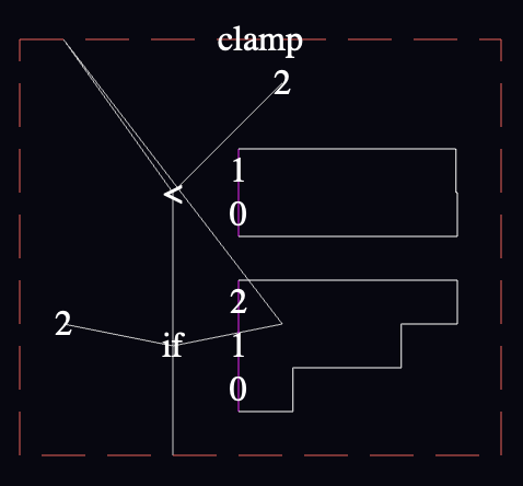
I decided to extend the earlier example with a function that clamps the sum to return no value larger than 2:
var clamp = function(num) {
  return num > 2 ? 2 : num
}
clamp(sum(repeat(3, function() { flip() })))
It came out like this:
Yeesh. "clamp" has to be the ugliest function I've ever seen. 😬
Anyway, some other notes:
The charts inside the definition of "clamp" are aggregated across every call to the function, and across every call site (though there's only one call site in this model). This seems like a good default, although several other useful ways to slice the data immediately spring to mind.
I fixed the wire coming out of the "flip" near the top, to make it clearer that it's not the same wire as the one connected to the edge of the function box. "flip" is connected to the function's output wire, whereas the other wire is connected to the "clamp" function itself. Better rendering is needed here.
The "clamp" node in the lower left is red to match the border of the "clamp" function's definition on the right. I think this works, though I need more examples to know if this information is useful enough to use up a color.
It would be consistent with the rest of the language to connect the "clamp" node to the definition of "clamp" on the right with a wire, but I'm not convinced that the extra lines are worth it yet.
Discussion of results
The elephant in the room is that I started with this modest WebPPL model:
var clamp = function(num) {
  return num > 2 ? 2 : num
}
and turned it into this:
It takes work to read, and I'm not happy about it:
The wires' connection points are difficult to make out. Connections to the function's inputs and outputs are particularly unsatisfying. In the end, I didn't render the little directional arrows or tiny overlaps that I had in my original drawings because I acutally wasn't sure that they were the right choice. I think I want to live with wires as-is for a bit before I commit, since I don't think the rendering will be as trivial as the other things in this sketch.
The straight-line shape of the wires forces you to contort the code to avoid confusing overlap—which I couldn't entirely pull off in this example because of the cross-crossed shape caused by the if-false-on-left/if-true-on-right convention I decided on.
The convention I proposed of putting the if-false branch on the left and if-true branch on the right prevent me from reusing the "2" node, because the first "2" is on the right and I want it on the left for the conditional below. I couldn't avoid the criss-cross for the function input (because I didn't think it was worth it to create a "dup" or repeater node), so I introduced a single bend in the wire so that it could approach the "if" from the right direction.
On the other hand, I can live with all of this for now because it meets my criteria: it represents a reasonably unambiguous language semantics that I'm confident that I can edit using commonly-available input devices. All right? So I'll address all this later. Perhaps by improving wire rendering beyond straight lines. Perhaps by being more flexible about the direction wires can enter a node (swap left and right sides of an if by adding those color or text tags?). Later, though.
What worked?
After seeing it digitally-rendered, I still feel comfortable that I can work with these function semantics. I think I may have incorporated a few too many degrees of freedom in the way wires can travel into and out of functions, but I can always rein that in later.
I love seeing what's going on inside the clamp function. It feels like an x-ray, like peering into a profile-guided optimizer, and like using a whole pile of multimeters. I love the reachability questions the charts pose merely by leaving the door to this information cracked open.
Conclusion
Expressive enough for the models I want to write (edit! explore!) first
Wires let you spread code out enough for all the charts I want to add
Being spread out makes it hard to read. D'oh! And duh. And "challenge accepted."